Holiday Office Door Decoration
There is a lot of spirit in the building I work in. It’s a really terrific environment. There is a core group of folks who find ways to do little celebrations throughout the year, and it makes work a genuinely fun place to come every day.
Among the events planned this holiday season is a door decorating contest. Now as the sole IT guy in my building, I have my own office space with a door and I’m kind of on my own. I’m not particularly creative or “crafty” but I started to think about how I could bring some nerd flavor to the contest. I knew I wanted to use an Arduino microcontroller and a few of the assorted electronic parts I have around the house. The thought occurred to me to create some type of Holiday Cheer-o-Meter.
The more I thought about it, the more excited I became. When it comes down to it, I wasn’t as concerned with competing – I just wanted to see if I could make my vision come together and actually work. I also thought this would be a fun project to bring the boys in on. I explained what I was thinking to them and Isaac immediately wanted to help with the circuit design and programming. The Sunday before Thanksgiving we got to work.

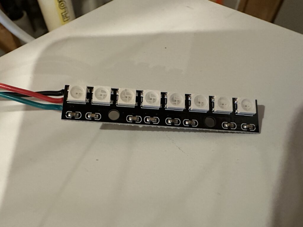
Being a holiday decoration, it’s going to have to incorporate some lights. It would be nice if I could run them all from the Arduino, and if I could do fancy things with at least some of them. I found some cool RGB LED arrays on Amazon that are controlled with a WS2812 chip. This means I could have 8 color-changing lights in a tight row while only using 1 of the control pins on the Arduino. That would become our “scanner.” While we were out with family at Homestead Gardens, I also found some very tiny (and inexpensive) battery-powered string LEDs. Since these used 3 AA batteries, they would be easy to run off of the 5V power rail in the Arduino.
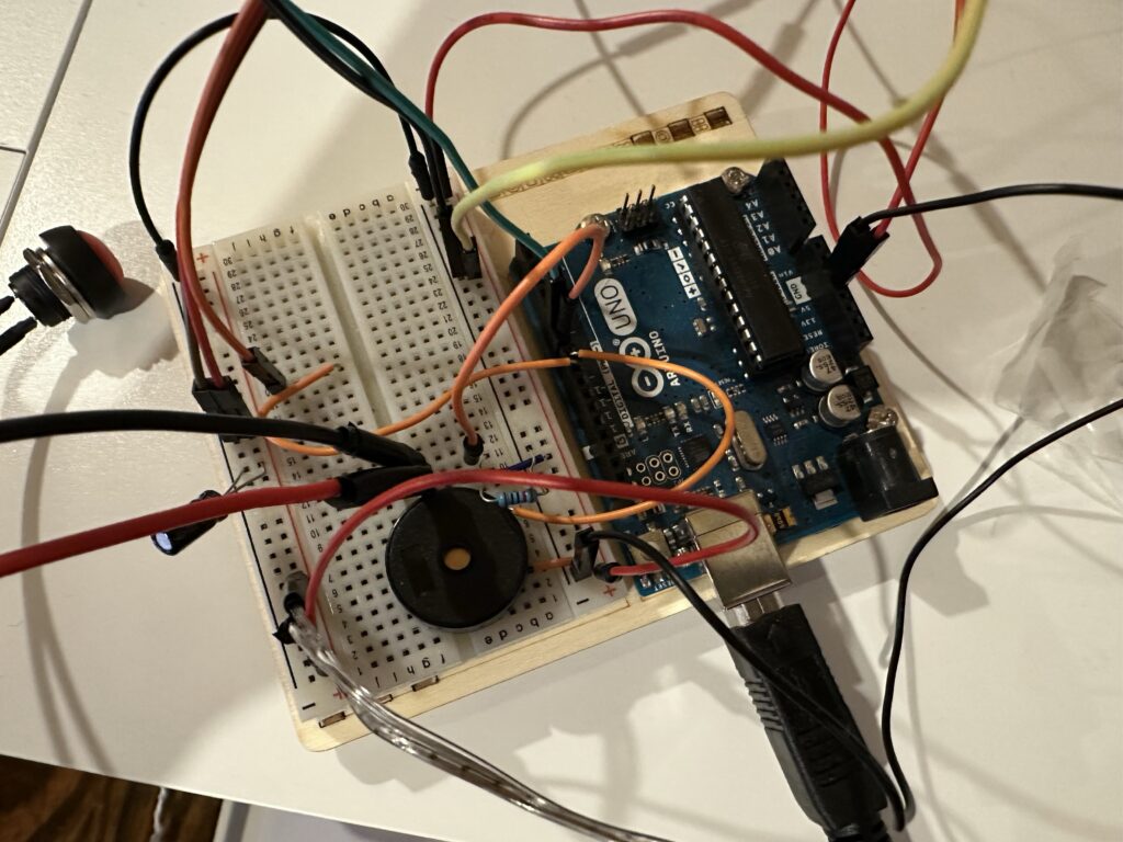
The meter itself would be made from a servo motor, allowing us to control the position in degrees with some simple code. For a fun twist, we also found a “pitches” library that allowed us to program music to play through a small piezo buzzer when the meter showed its reading.
All told, it took a little more than 2 hours to do a tiny bit of soldering, put together the circuit on the breadboard, and set up our microcontroller program. It took much longer for me to get the whole thing to look, well, pretty.
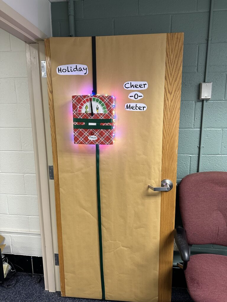
The user interface is extremely simple. A single button starts the “scan”.
Once the button is pressed, the LEDs on the front cycle through red and green flashing sequences. A pseudo-random number between 0 and 4 is generated. If 0 is picked, the whole system bottoms out and the meter displays the Grinch sequence. If a number greater than 0 is picked, another pseudo-random number is pulled between 90 and 180 to set the degree of cheerfulness.
I like to think that the pseudo-random number generator in the Arduino can be affected by the “vibes” of the environment. Quantum entanglement and all. 🙂
This project was extremely fun to make. Microcontrollers like the Arduino make little projects like this pretty accessible these days. So far, the response at the office has been very positive. I’ll be sure to post an update once the competition is over.